Every computer has one – a power supply unit (PSU). Desk top computers, workstations, gaming rigs, laptops, and servers all incorporate a power supply. The main purpose of a PC power supply is to convert AC mains power into the DC voltages required to operate the various components inside a computer (motherboard, CPU, video card, memory, drives, etc.). And a power supply must be designed and built to insure compatibility, stability, and control for starters.
Have you ever wondered what goes on inside a power supply? We frequently use phrases like “a modern topology with half-bridge LLC Resonant Converter, Synchronous Rectification with DC-to-DC voltage regulators”. So what does that mean and what is topology anyway? We’re glad you asked – read on and we will explain!
Note: one of the challenges we face when publishing a “general theory” article is finding the right balance between technical detail and fluff. Over the years we have received many comments about PCPerspective’s power supply reviews. Some readers want more technical details while others complain there are too many. We try to find the right balance to remain informative and useful without boring the average PC enthusiast with technical minutia.
Form Factor
The form factor is a specification that defines both the physical and electrical requirements a PC power must meet to insure cross market compatibility. This allows numerous after market power supply manufacturers to compete for your custom build and upgrade dollars. When you purchase a PC power supply you can rest assured that it will be compatible (physically and electrically) with your PC.
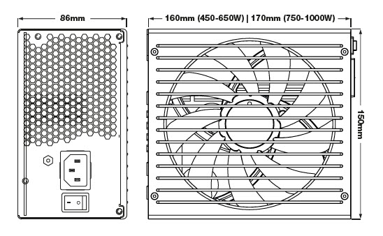
For example, one of the recent Power Supply Design Guides for Desktop Platform Form Factors (created by Intel) is the ATX12V Power Supply Design Guide, v2.4, which describes the specifications for the ATX form factor.
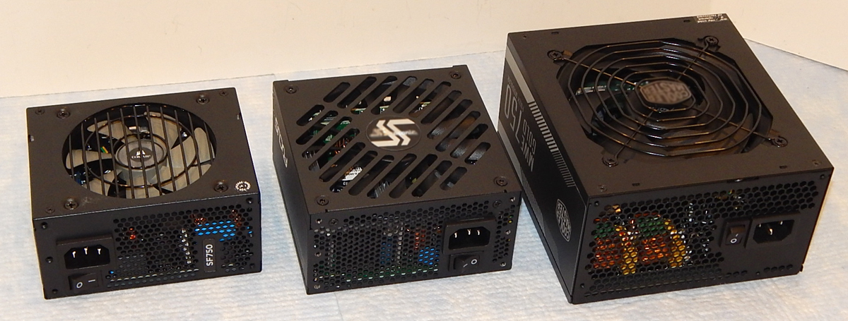
(SFX, SFX-L and ATX Form Factors)
(ATX Physical Dimensions)
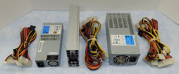
(1U and 2U Server Style PSUs)
In addition to ATX, two other popular form factors used in desk top PCs include the SFX and SFX-L (extended or lengthened) form factors. 1U and 2U form factors are most often used in servers. On the other hand the power supply in a typical laptop computer is proprietary to a particular manufacturer (built into the main board with or without an external power brick) and are not interchangeable.
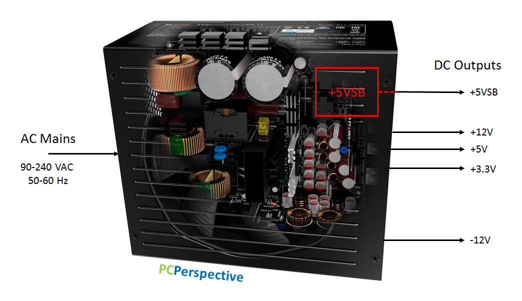
The diagram above shows the basic electrical specifications for a typical PC power supply. AC mains power in; five separate DC voltages out. Note the +5VSB section is a small stand-alone power converter inside the larger PSU. Its output stays on anytime the PSU is connected to AC mains with the master power switch turned on, even when the main PSU is in standby and the computer is shut down.
Please continue reading our article on How A PC Power Supply Works!
Basic Control
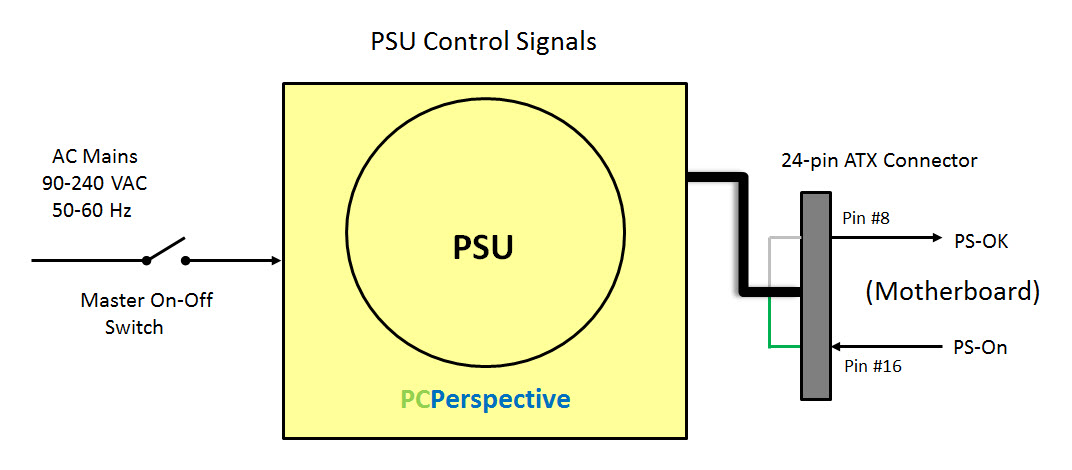
To be useful a power supply must be controlled. Being able to turn the power supply on and off is a basic requirement. Most PC power supplies use a manual on-off switch to control the AC mains power coming into the PSU. Once switched on the PSU and computer (motherboard) work together to power up the PSU and PC and shut them down at the user’s request.
When you press the main power-on button on the front of your computer it sends a signal to the motherboard which then sends a signal via pin #16 (green wire) in the 24-pin ATX connector to the power supply. When pin #16 goes low (ground) the PSU starts up, performs some quick internal self-tests, and then sends a signal back to the motherboard through pin #8 (gray wire) to let it know the “Power is Good”. As long as pin #16 is held low the PSU should stay on. At the end of the PC shutdown procedure pin #16 will no longer be pulled low and allowed to float high, which causes the PSU to turn off.
PC power supplies also incorporate a number of internal safety circuits that monitor the power supplies operation: Over Current Protection (OCP), Over Voltage Protection (OVP), Under Voltage Protection (UVP), Over Power Protection (OPP), Over Temperature Protection (OTP), and Short Circuit Protection (SCP). If any of these parameters exceed their programmed set-points a fault signal will be triggered to shut down the PSU.
Switching Basics
Linear Power Supply
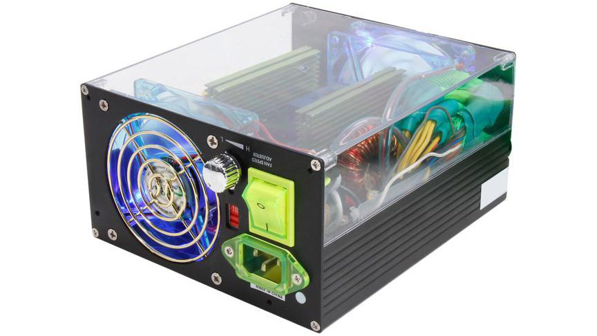
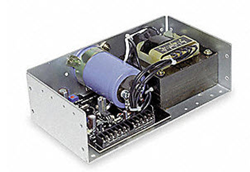
Back in the days before transistors came into widespread use power supplies were based on a linear design. Linear power supplies were used in early radios and TVs along with all sorts of electrical devices. They are still in use today and are often big, heavy, and relatively expensive, not to mention inefficient (60~70%).
For example the linear power supply in the photo above provides a 12 VDC output with 6A capacity (72W) and weighs about twelve pounds and sells for $250 USD. Just think what a 600W or more PSU would be like!
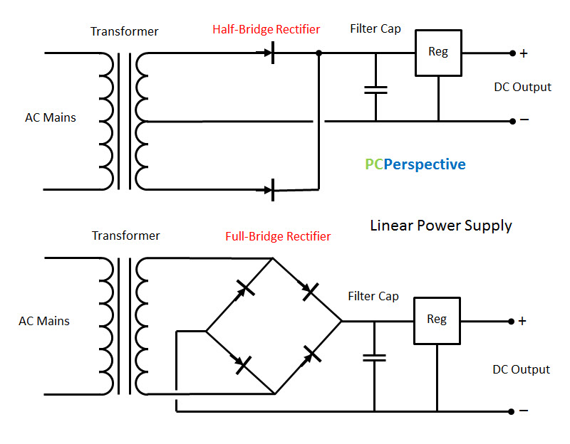
The design and construction of a linear power supply is relatively simple. The AC mains power goes in through a large transformer where it is stepped down to the required DC voltage level. Separate windings/taps are necessary for each voltage. In reality several transformers might be used to provide the five different DC outputs. The stepped down voltage is still AC so now it needs to be rectified – turned into pulsing DC. The final step is to filter the output and smooth out the remaining AC ripple and noise. Most modern designs now include a regulator to help control the DC voltage. The main limiting factor of the linear power supply is that it operates at the AC mains frequency; 50-60 Hz depending on your location. Transformers, capacitors and inductors all have to be very large to operate in this frequency range.
Note in the diagram above there are two different designs shown for the rectifier stage: half-bridge and full-bridge. This topology also applies to switching power supplies although MOSFETs are used instead of diodes.
Switch-Mode Power Supply (SMPS)
Modern PC power supplies are based on a switch-mode power supply design and are commonly referred to as switching power supplies. A major advantage of a switching power supply is that it is designed to operate at much higher frequencies (50 kHz – 1 MHz). And since the size of the transformer, capacitors and inductors are inversely proportional to the operating frequency; these components can be significantly smaller, lighter, and less expensive.
(Courtesy of be quiet!)
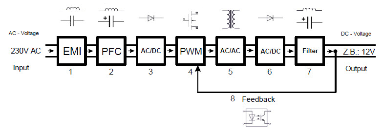
A PC switching power supply accomplishes this feat in multiple steps. First the incoming AC mains power is filtered (#1) to remove residual Electromagnetic Interference (EMI). Then the Power Factor (PF) is actively adjusted to maintain a PF close to 1.00; the waveform of the current is held in close synch with the voltage waveform (#2). Next, the incoming power is converted to DC (#3). High-power, high-efficiency power transistors (MOSFETs) are used to convert the DC back into AC (#4) by “switching” the DC power on and off at high frequency (~400 kHz). These switching transistors are controlled using a Pulse Width Modulation (PWM) feedback signal (IC) from the output to help regulate the final voltage. The high-frequency square wave produced is then stepped down to the required voltage by a transformer (#5) and then rectified, converted to DC (#6) and filtered for output (#7). This is a very simplified overview of SMPS operation. Now, let’s see what this looks like inside a modern PC power supply.
Under the Hood
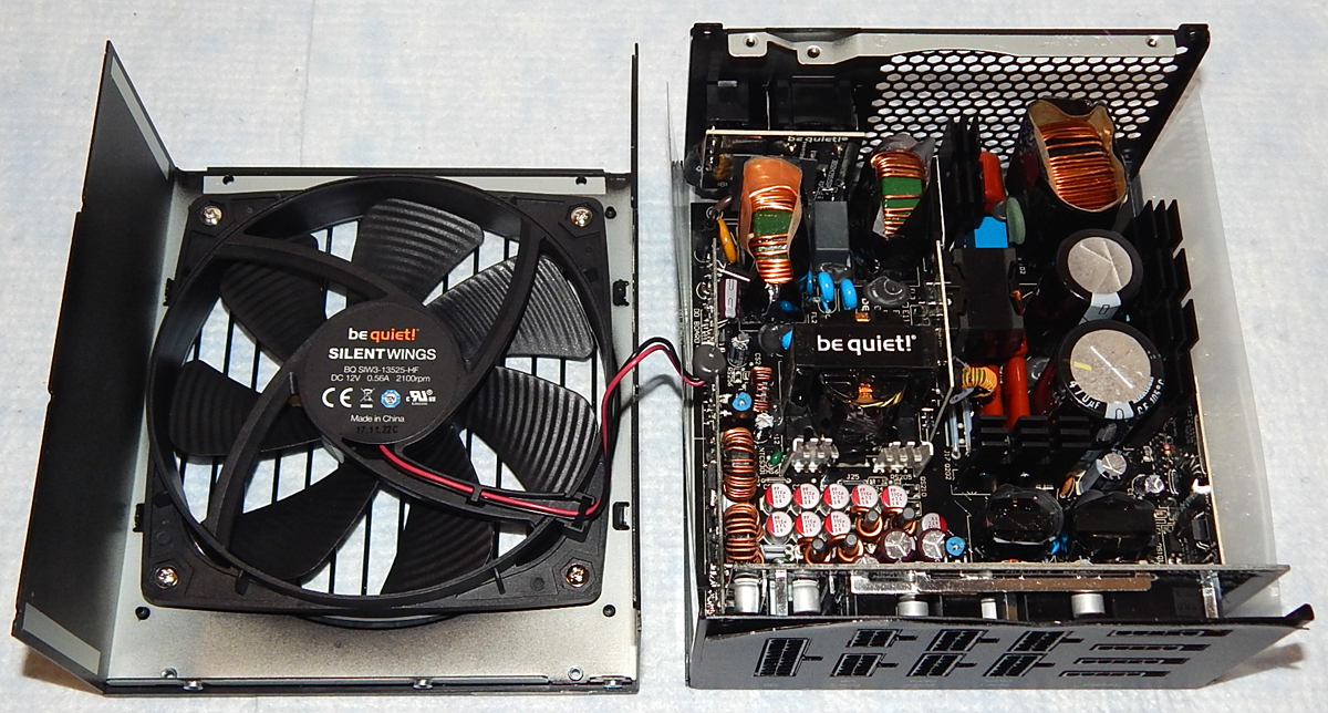
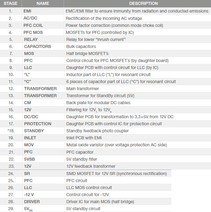
Part of the review process at PCPerspective involves opening a PSU case (yes, it voids the manufacturer’s warranty) and giving you the reader an opportunity to see what it looks like on the inside. A quick look under the hood can reveal a lot about a PSU (construction, components, layout, soldering, etc.).
(Courtesy of be quiet!)
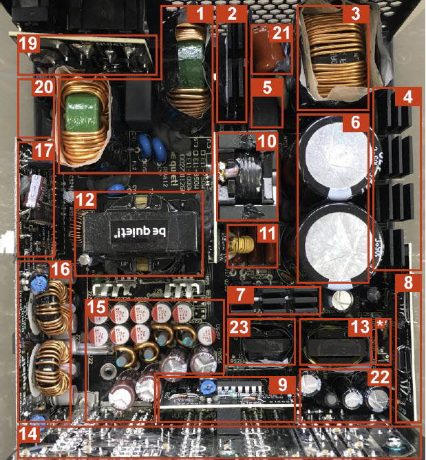
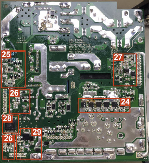
These two diagrams highlight some of the components and their functions inside the 850W be quiet! Straight Power 11 power supply we recently reviewed (shown in the photo above).
(Courtesy of be quiet!)
(Courtesy of be quiet!)
We frequently include some verbiage that describes the topology (how the circuit is designed and assembled) something like: “the manufacturer is using a modern half-bridge LLC Resonant Converter, Zero Switching (ZS), Synchronous Rectification (SR) design along with DC-to-DC converters located on a daughter card to provide good voltage regulation and high efficiency”. Now let’s dig a little deeper and see what that really means.
Half-Bridge LLC Resonant Converter
(Courtesy of be quiet!)
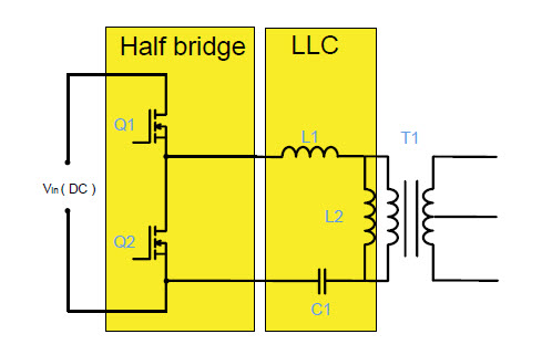
The beginning statement contains two parts, half-bridge and LLC Resonant Converter. Note the similarity to the basic half-bridge rectifier circuit shown previously in the linear power supply section. (Four MOSFETs could alternately be used to create a full-bridge rectifier circuit.)
The half-bridge configuration uses two MOSFETs to create high frequency square wave alternating current, which is then smoothed out by a LLC circuit to produce a nearly perfect sine wave before it goes into the main transformer. The term LLC comes from (LLC=L1+L2+C1) inductor, inductor, capacitor (L is inductor and C is capacitor).
This is referred to as a LLC Resonant Converter. The configuration of inductors and capacitor in the LLC section form a tank circuit, which has a resonant frequency. The LLC Resonant Converter in a PC SMPS usually operates at a higher frequency than the resonant tank frequency.
Some advanced LLC designs not only use Pulse Width Modulation (PWM) to drive the MOSFET switching transistors, but also employ Frequency Modulation (FM) to adjust the power transformation. Starting at a 10 to 15 percent load, the high-performance LLC circuit modifies the frequency, producing better efficiency, with the optimal results being reached with higher frequencies at low loads and lower frequencies at high loads.
Zero Switching
(Courtesy of be quiet!)
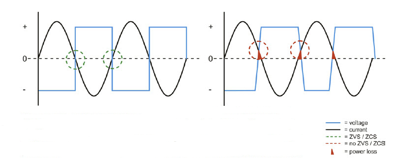
Many modern high-performance designs feature Zero Voltage Switching (ZVS) and Zero Current Switching (ZCS) for increased operating efficiency. To accomplish this the actual point of switching occurs at zero volts, zero current (green circles in diagram above). Traditional topologies cannot precisely control the switching point, resulting in switching losses (red circles). Switching with ZVS/ZCS is lossless and results in improved efficiency.
Synchronous Rectification (SR)
(Courtesy of be quiet!)
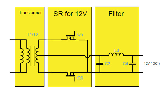
After the main transformer, the alternating current is rectified and becomes the DC current that PC components require. This is achieved by using two or more (depending on wattage) MOSFETs synchronized using a dedicated IC.
DC-to-DC Convertors
(Courtesy of be quiet!)
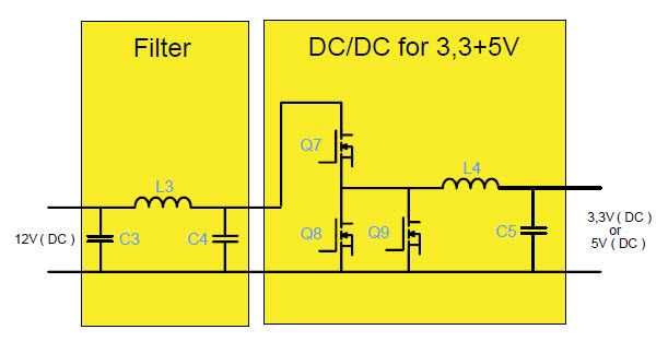
Most modern PC power supplies use DC-to-DC converters to produce the +3.3 VDC and +5 VDC outputs. Instead of generating the three principle voltages (3.3V, 5V and 12V) from AC on the primary side, the 3.3V and 5V outputs are generated from 12 VDC after the main transformer. This helps increase the overall efficiency of the power supply.
+12V Single vs. Multiple Rail Configuration
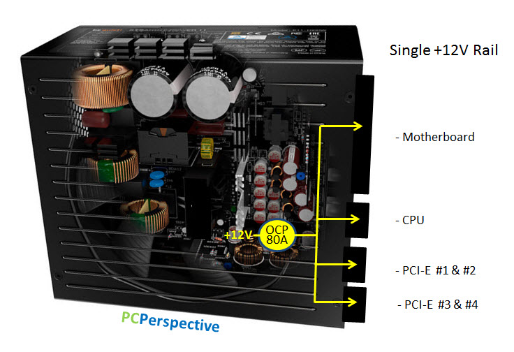
Back in 2003 one of the first power supplies I reviewed was a 350W Seasonic unit. It featured a single +12V output that could deliver up to 19A (228W).
The PSU illustrated above incorporates a single +12V rail capable of delivering power to all the output cables/connectors. The combined OCP set point is 80A. It doesn’t matter which cable/connectors are used to power components. The full 80A is available to any of them.
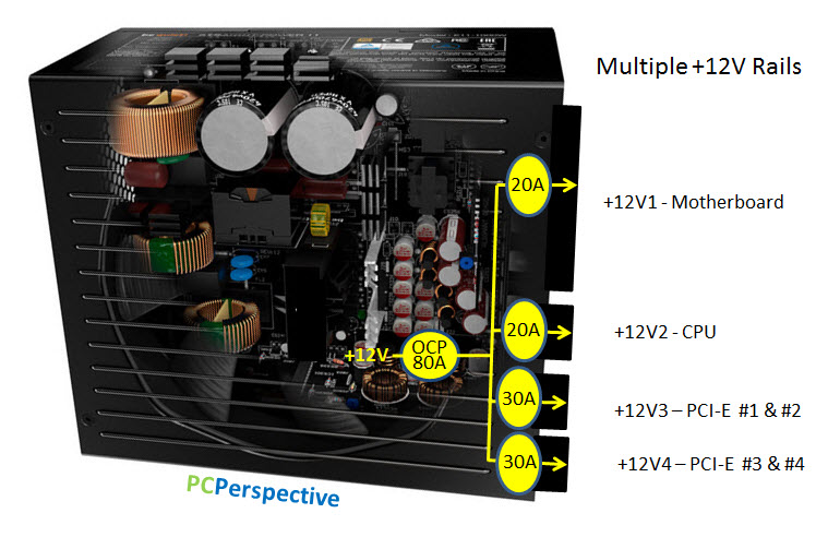
Over the years as PC power demand has increased the output capacities of PC power supplies also increased, especially on the +12V output. However, concerns arose that too much power could be dangerous (arc-flash, fireball, ejected molten metal) if a short circuit or other fault occurred. Guidelines were proposed to limit any single output to 240 watts. When applied to the +12V rail this works out to be 20A (12V x 20A = 240W). Manufacturers began building power supplies with multiple +12V outputs to comply. Note this was a guideline, not a law.
However it wasn’t long before many end users started running into problems with their power supply shutting down and apparently not working. In many cases the problem was one particular +12V output was being overloaded even though the total +12V capacity was not being used.
In this example the PSU features multiple +12V rails, each protected by its own current limiter. No single output can pull more than 20A or 30A while the combined OCP set point is still limited to 80A.
A big part of the problem with multi-rail configurations was that manufacturers had to decide how the total +12V power would be distributed. For a multi-rail output power supply they had to decide which +12V outputs would supply all the specific cables and connectors dedicated to powering components (CPU, graphic adapters, drives, etc.). This ultimately determined how much power was available to each component. If the end user’s configuration didn’t match the manufacturer’s norm then problems could occur.
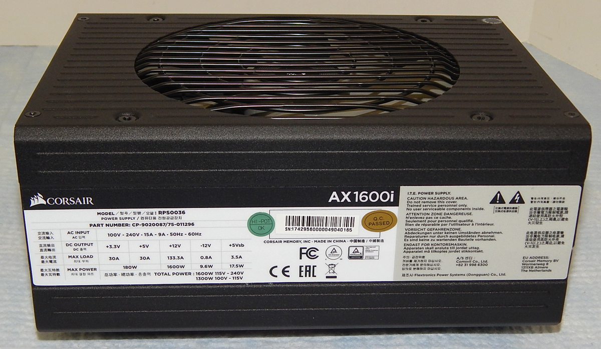
Eventually the majority of manufacturers have gone back to single rail +12V outputs. For example the Corsair AX1600i PSU can deliver up to 133.3A (1600W) on the single +12V output. (Note: the AX1600i gives users the option to set current limits on the +12V rails if desired.)
Today the safety protection circuits in most modern, enthusiast grade PSUs are fast enough they can sense a fault (SCP or OCP) and shut the power supply down before enough energy can be delivered to cause a dangerous problem. For example, when I test the Short Circuit Protection circuits in a power supply, they typically react so fast I barely get a spark when creating a direct short (but I still wear safety glasses).
A “Good” Power Supply
And last but not least, a question we are frequently asked is “What makes a good power supply good?” Here are a couple things to consider when shopping for a PSU.
Requirements:
• Compatibility: ATX12V v2.4, EPS 2.92 compliant
• Max operating temp: prefer 50°C
• Voltage regulation: within ±2% of the recommended guidelines
• AC Ripple & noise suppression: below 50% of recommended guidelines
• Efficiency: at least 80 Plus Gold certified (92%)
• Noise: at least 120mm fan with good bearings (FDB or Ball)
• All Japanese made capacitors rated for 105°C
• Warranty: at least 5-years
• Price: shop around to find the best match for your budget
Optional:
• Fan-less mode (at low to mid power)
• Semi-modular or full modular cables
• Size: stay with ATX unless you need a smaller unit
Note: I personally prefer to have a PSU cooling fan spinning at all times to keep a little air moving. And when it comes to cables I prefer semi-modular with a fixed 24-pin ATX, 4+4 pin CPU, and a pair of fixed PCI-E. Everything else can be modular.
In closing we hope you have found this article interesting and informative. And again, our thanks to be quiet! for letting us use some of their graphics. Power On!




Thank you! I really appreciate an up-to-date refresher on one of the most important parts of a PC build. This is not one of the components that you should try to save money on when building a system.